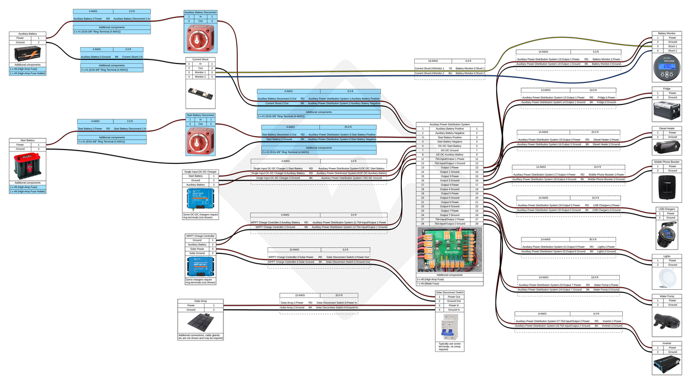
Auxiliary Power Distribution System with Multiple Chargers Wiring Diagram
Refer to this diagram when connecting the following chargers:
- Victron Orion-Tr Smart DC-DC Charger (non-isolated)
- Victron BlueSolar MPPT 100/30 or 100/50
- Renogy Rover 60 Amp MPPT Solar Charge Controller
- Renogy 12V 20A/40A/60A DC to DC On-Board Battery Charger
- Any other single-input DC-DC charger
Our Start and Auxiliary Battery Connection Kit includes all of the fully assembled cables, fuses, and battery disconnect switches highlighted in blue.
Battery System Wiring Diagram
 Download Battery System Wiring Diagram PDF
Wire sizes and lengths should be calculated based on the requirements of your system, the sizes listed in these diagrams are examples only. When planning out your build, use our battery system current and power calculator to determine the total current and power requirements for your accessories as well as our our wire and cable size calculator and wire and cable size table for help figuring out what size wire and cable to use!
Battery System Parts List
| Qty | Item |
|---|---|
| 1 | Auxiliary Battery |
| 1 | Auxiliary Power Distribution System |
| 1 | Battery Monitor & Current Shunt |
| 1 | DC-DC Charger |
| 1 | MPPT Charge Controller |
| 1 | Solar Array |
| 1 | Solar Disconnect Switch |
| 2 | Battery Disconnect Switch |
| 2 | High-Amp Fuse Holder |
| 5 | High-Amp Fuse |
| 6 ft | Wire, 8 AWG, BK |
| 6 ft | Wire, 8 AWG, RD |
| 7 | Blade Fuse |
| 10 | 5/16-3/8" Ring Terminal (4 AWG) |
| 23 ft | Wire, 10 AWG, BK |
| 23 ft | Wire, 10 AWG, RD |
| 38 ft | Wire, 4 AWG, BK |
| 43 ft | Wire, 4 AWG, RD |
| 95 ft | Wire, 14 AWG, BK |
| 95 ft | Wire, 14 AWG, RD |