APDS Manual and Installation Guide
Getting Started
Installing an auxiliary battery system in your truck or van doesn't have to be super complicated. The Auxiliary Power Distribution System and our wiring kits ensure your connections are routed correctly. By following this guide you can be confident that your auxiliary battery system is properly installed.
When planning out your build, use our battery system current and power calculator to determine the total current and power requirements for your accessories. For figuring out what size cable you need, check out our wire and cable size calculator and wire and cable size table! We also have a guide to common components such as DC-DC converters, inverters and other equipment used to build battery systems.
If you're not sure what DC-DC charger, inverter, wiring kits, etc to purchase for your system please refer to the frequently asked questions or contact us for recommendations. If you already have your equipment or know what you want and haven't purchased your APDS or wiring kit yet, please provide your DC-DC charger and inverter model numbers when you fill out the order form and we'll check if additional cable is required for your install before we finalize your order.
- This guide is not a replacement for basic electrical knowledge. Read the manufacturer's instructions for all of your equipment before beginning your installation. If you're new to this kind of thing, check out our Electrical System Basics series of posts for an introduction!
Making connections to the APDS
- Strip the wires/cables to the appropriate length for the connector. The length of exposed conductor can be verified by using the guide molded into the side of the connector
- Large connectors: 3/4 in ≈ 19 mm
- Medium connectors: 1/2 in ≈ 12 mm
- Small connectors: 1/4 in ≈ 10 mm
- Lift up on the lever for the connector. The levers on the large connectors can be very stiff. If needed, use two hands to brace against the connector to get some leverage. Do not use tools to move the levers
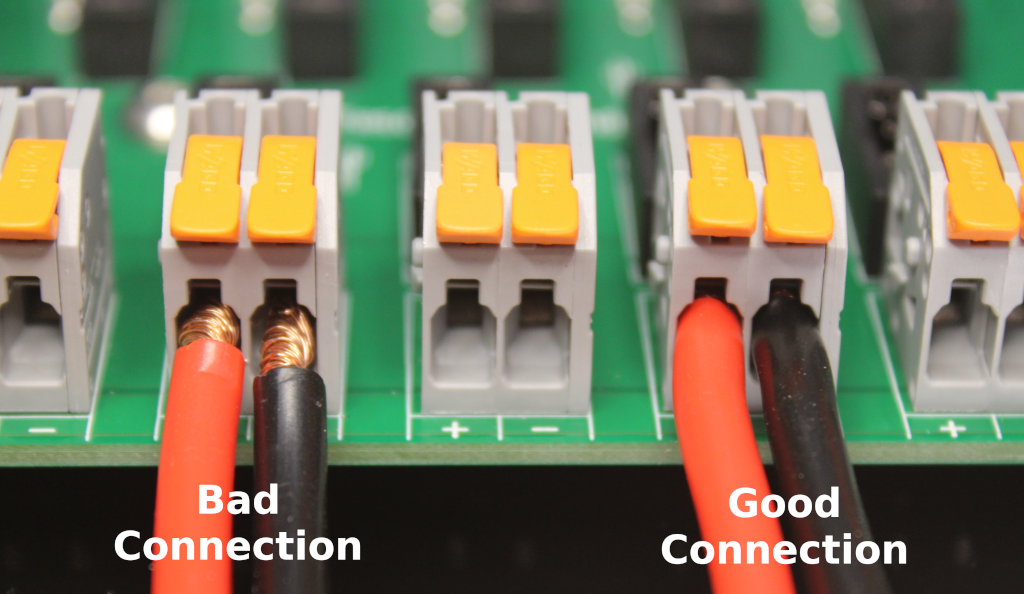
- Insert the cables. All of the wire strands must be fully inside the connector body. The wire insulation should be slightly within the connector body as shown in the picture above. Freshly stripped cable can help the wire strands go inside of the connector easier, if necessary trim and re-strip the wires or cables to ensure a solid connection
- Press down on the lever until flush with the connector body to complete the connection. The large connectors can snap shut with a large amount of force - keep your fingers clear
- If you have a multimeter you can perform a continuity check by inserting the multimeter probe into the holes in the levers and connector body
- Give the wires/cables a gentle tug to verify they are connected securely
- Strain relief is highly recommended. Whether you use our strain relief brackets, screw mount cable ties, cable mounts or something else entirely is up to you
Tools for Installation
At a minimum, you will need:
- Basic hand tools - screwdrivers, socket set, etc
- Wire stripper/cutter for 10 to 24 AWG wire
- Utility knife or cable stripper for 4 to 8 AWG cable
Depending on your vehicle and accessories you may also need the following:
- A small crimp tool to install ring/spade terminals on the accessory side of some connections, particularly with USB chargers and lighting. Ratcheting crimp tools are recommended as they create much more reliable connections
- Heat gun (or hairdryer) for adhesive heat shrink terminals. A lighter will get the job done but won't produce the best looking results
- Wire fish/fish tape will make cable runs easier where access is tight
- A multimeter or voltage/circuit tester will be helpful for troubleshooting, if necessary
Materials for Installation
- Auxiliary Power Distribution System
- Start and Auxiliary Battery Connection Kit
- Bolts and/or screws to mount equipment. The APDS mounting bracket has several 1/4 in (6.5 mm) holes suitable for up to size M6 screws/bolts
- Wire ties, cable mounts, wraps, etc for cable management
- 8 to 10 AWG (or larger) red and black wire for connecting your solar panels. Check the manual for your equipment to determine proper sizing and maximum lengths
- 12 to 16 AWG red and black wire for connecting your accessories. Check the manual for your equipment to determine proper sizing and maximum lengths
- Depending on your specific accessories, ring/spade terminals or may be required for the accessory side of the connection. Adhesive heat shrink terminals are recommended as they create much more reliable connections
- Wago 221 lever-nuts for making splices and other connections
- Solar disconnect switch/circuit breaker
- Cable glands and grommets for making connections on the exterior of the vehicle (e.g. for solar panels, camp lights, etc)
- Cable pulling lube for routing cables through grommets in the vehicle's firewall
Our battery wiring kit includes the cables you will need to connect your start and auxiliary batteries but do not include the cables needed to connect some DC-DC chargers (such as the Redarc Manager30/BMS1230S3). DC-DC chargers with cables hard-wired (such as the Redarc BCDC1240D) can simply be connected directly to the APDS. Specify your DC-DC charger and inverter model numbers when ordering your kit and we'll check if additional cable is required for your install before we finalize your order. Up to size 4 AWG cable can be used with the APDS.
Selecting an Installation Location
Several considerations must be taken into account when selecting an installation location for your equipment:
- Safety: Batteries can deliver extremely high electrical currents which are easily capable of causing fires and other dangerous conditions. All components must be physically protected from short circuits and other hazards that would result in poor electrical and mechanical connections. The levers on the APDS connectors are difficult to operate unintentionally but must be protected from bumping, pulling, etc.
- Protection: Lithium batteries and the APDS are not designed to be exposed to high levels of dust and are not water resistant
- Cooling: DC-DC chargers and other equipment may generate large amounts of heat and should not be placed in a completely enclosed area
- Distance: All cable and wiring runs should be as short as reasonably possible to reduce power loss
- Ease of access: Will you have enough room to route cables? How difficult will it be to access the APDS to add more equipment, move connections or replace fuses?
Component Installation
Once you have identified installation locations for your equipment the next step is to temporarily mount the equipment within your vehicle to check for fit and verify that cables may be routed effectively. 4 AWG cables in particular have a limited bend radius and may be very difficult to route in tight spaces. If you have a small amount of space for your equipment you may want to route your cables before permanently mounting any equipment to make absolutely certain enough clearance is available.
The APDS can be mounted in any convenient orientation and within an enclosed space if necessary. The connectors will require a small amount (less than 1 inch) of vertical clearance to fully open.
APDS mounting bracket template
The mounting bracket has several 1/4 in (6.5 mm) holes and slots suitable for up to size M6 screws/bolts (not included). Do not modify the mounting bracket by drilling additional holes under the circuit board.
Wiring Diagrams
Wire sizes and lengths should be calculated based on the requirements of your system, the sizes listed in these diagrams are examples only. When planning out your build, use our battery system current and power calculator to determine the total current and power requirements for your accessories as well as our our wire and cable size calculator and wire and cable size table for help figuring out what size wire and cable to use!
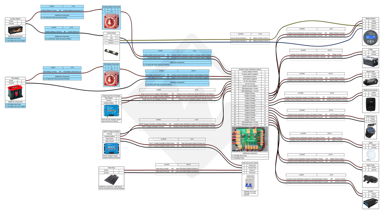
Dual Input DC-DC Charger
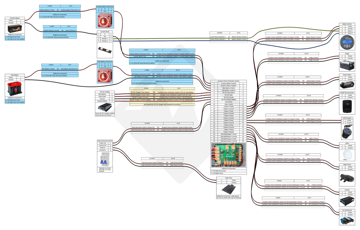
Multiple DC-DC Chargers
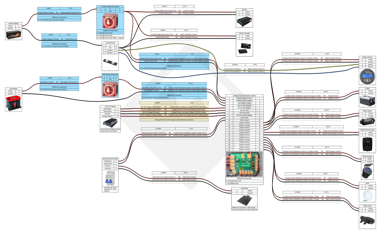
High Current Bypass
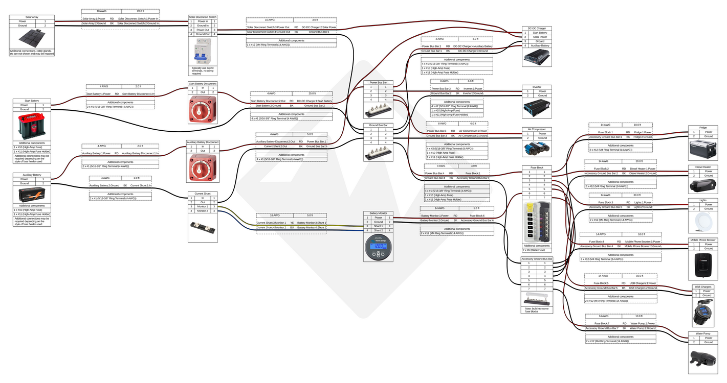
Standard Install with Bus Bars (for comparison)
Our Start and Auxiliary Battery Connection Kit includes all of the cables and parts you will need to connect your start and auxiliary batteries (highlighted in blue on the diagrams above). Additional disconnect switches and cables/kits may be required depending on your specific equipment and how you plan to use your vehicle.
We recommend that light bars and other accessories which would generally be used while the engine is running be connected directly to the vehicle's primary 12V electrical system instead of the auxiliary battery system. A Dual MRBF terminal block can easily be used to connect and fuse both your auxiliary battery system's DC-DC charger as well as a power system controller (Switch Pros/S-POD) or something simpler like a waterproof fuse block.
Need a custom kit or want to connect something not shown here? Contact us for assistance!
Connecting an Auxiliary Battery and Battery Monitor
- Before connecting or disconnecting a battery ensure all previously connected accessories have been disconnected or completely powered off
Connecting the positive battery terminal, fuse and battery disconnect switch:
- Ensure the Auxiliary battery disconnect switch is in the "off" position
- Install the terminal cover on the Auxiliary battery cable (red)
- Auxiliary battery cable (red) to APDS input "Aux Batt +"
- Ensure the terminal cover is entirely covering the cable lug and terminal stud
- Auxiliary battery cable (red) to Auxiliary battery disconnect switch output
- Auxiliary battery disconnect jumper (red) to Auxiliary battery disconnect switch input
- Auxiliary battery (150A max) MRBF fuse block output to Auxiliary battery disconnect jumper (red)
- Auxiliary battery positive terminal to Auxiliary battery (150A max) MRBF fuse block input
Connecting the negative battery terminal and battery monitor / current shunt:
- Auxiliary battery negative terminal to Auxiliary battery shunt jumper (black)
- Auxiliary battery shunt jumper (black) to Current shunt input
- Current shunt output to Auxiliary battery cable (black)
- Auxiliary battery cable (black) to APDS input "Aux Batt - (shunt)"
Battery monitors usually have one cable or two more wires which connect directly to the current shunt in addition to the battery connections (this will vary depending on your specific monitor). Please refer to your battery monitor's manual for specific instructions on how to place those connections. The battery monitor power cable may be connected to any of the 15A outputs on the APDS or directly to the battery using a separate fuse and fuse holder. Note that if your battery monitor is powered via the APDS, turning the auxiliary battery disconnect switch to the "off" position will also turn off the battery monitor.
Connecting a Start Battery
Both of the start battery cables will need to be routed from your APDS, through the vehicle firewall and to the start battery. Using a chassis ground point inside the cab or on the frame is not recommended. Be sure to route the cables before connecting the cables to the start battery.
Tip: when routing cables through a difficult to access grommet in the vehicle's firewall, use cable pulling lube and a short (5-10 ft) wire fish/fish tape to route the cables
Connecting the positive battery terminal, fuse and battery disconnect switch:
- Ensure the Start battery disconnect switch is in the "off" position
- Start battery cable (red) to APDS input "Start Batt +"
- Start battery cable (red) to Start battery disconnect switch output
- Start battery disconnect jumper (red) to Start battery disconnect switch input
- Start battery (30-75A) MRBF fuse block output to Start battery disconnect jumper (red)
- Start battery positive terminal to Start battery (30-75A) MRBF fuse block input
Connecting the negative battery terminal:
- Start battery negative terminal to Start battery cable (black)
- Check your vehicle's owner manual to determine if a specific ground point is recommended
- If your vehicle has a battery management system ensure the ground connection is connected so that current flows through the battery sensor instead of directly to the negative battery terminal
- Failure to follow the vehicle manufacturer's recommendations can result in damage to your vehicle
- Start battery cable (black) to APDS input "Start Batt -"
Connecting Solar Panels
At least 8 or 10 AWG cables are recommended, generally speaking bigger is better in order to keep voltage drop to a minimum (our wire and cable size calculator can help you figure out minimum cable sizes). For example, a 200W solar blanket would produce a maximum output of 11A at 18V. Given a 20 ft one way (40 ft round trip) cable even 8 AWG would result in a greater than 2% voltage drop. While 8 or 10 AWG is safe for this application, 6 AWG cable would be preferable from an efficiency and performance standpoint.
Before connecting your panels, ensure the solar disconnect switch is in the "off" position. On the interior of the vehicle, solar power connections will be fairly straightforward:
- Solar panel/Blanket/Array positive to Solar disconnect switch/breaker positive
- Solar disconnect switch/breaker positive to APDS input "Solar +"
- Solar panel/Blanket/Array negative to Solar disconnect switch/breaker negative
- Solar disconnect switch/breaker negative to APDS input "Solar -"
Connecting a DC-DC Charger
- Ensure the engine is not running and the key is in the "off" position
- Ensure the Solar disconnect switch/breaker is in the "off" position
- Ensure the Start battery disconnect switch is in the "off" position
- Ensure the Auxiliary battery disconnect switch is in the "off" position
- Check the charger manual for the Output fuse rating. Ensure the correct fuse is installed on the DC-DC output fuse holder on the APDS. (MIDI fuse installation instructions)
- If your kit included cables for your DC-DC charger, connect them now (black to ground, red to the other connections). DC-DC chargers with wiring harnesses or cables hard-wired (such as the Redarc BCDC1240D) may be connected directly to the APDS
- DC-DC charger start battery input to APDS input "DC-DC In Start Batt +"
- DC-DC charger solar input to APDS input "DC-DC In Solar +"
- DC-DC charger output to APDS input "DC-DC Output Aux Batt +"
- DC-DC charger ground to APDS input "DC-DC Ground -"
You may now turn the disconnect switches to the "on" position and test your DC-DC charger!
Connecting Accessories (Inverter, Fridge, etc)
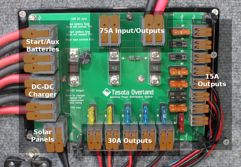
The APDS has 15 outputs to use for connecting your accessories: 2 large (up to 75A each), 5 medium (up to 30A each) and 8 small (up to 15A each).
- The large connectors along the top of the APDS will typically be used for:
- Inverter
- Air Compressor
- Battery Charger / Power Converter
- The medium connectors along the bottom of the APDS will typically be used for:
- 12V Outlets
- Light Strings
- Diesel Heater
- Radios
- The small connectors along the side of the APDS will power your remaining accessories:
- Fridge
- Water Pump
- USB Chargers
- Mobile Phone Booster
- Battery Monitor
The following size wires/cables may be used for each connector:
- Large: 4 to 18 AWG = 0.75 - 25 mm²
- Medium: 8 to 24 AWG = 0.2 - 10 mm²
- Small: 12 to 24 AWG = 0.2 - 4 mm²
To connect an accessory:
- Ensure the accessory is switched "off" to ensure that no arcing/sparking occurs when the cables or wires are inserted into the connector
- Some accessories will come with cigarette lighter 12V plugs. If necessary, cut off the plug so that you have two bare wires
- Before you cut off the plug, make sure you've identified the positive and negative wires in the power cable. If they are not labeled the plug can be disassembled to identify polarity, or a multimeter can be used to check continuity between the two ends of the wire
- Select an output connector to use. Check the manual for your accessory to determine what fuse rating to use and install one into the fuse holder if necessary. (MIDI fuse installation instructions)
- Connect the positive power cable to the desired output
- Connect the negative power cable to the desired output
- Fuses must be removed if no load is attached or when entirely disconnecting a load to ensure unused terminal blocks are not live
Connecting a Battery Charger or Power Converter
- The APDS must never be used to combine multiple batteries into a single battery bank
Installing or Replacing a MIDI Fuse
- Ensure the accessory is switched "off"
- Ensure the engine is not running and the key is in the "off" position
- Ensure the Solar disconnect switch/breaker is in the "off" position
- Turn the Start battery disconnect switch to the "off" position
- Turn the Auxiliary battery disconnect switch to the "off" position
- Remove the thumb screws holding on the fuse cover
- Remove the nuts holding the fuse in place
- Remove and replace the fuse
- Replace the nuts holding the fuse in place. Tighten the nut until the washer is flat. A standard locking washer and flat washer may be used to replace the locking belleville washers if they are misplaced or become damaged. Do not use thread locker for these fasteners.
- Replace the thumb screws holding the fuse cover in place
- Turn the Auxiliary battery disconnect switch to the "on" position
- Turn the Start battery disconnect switch to the "on" position
- Turn the Solar disconnect switch/breaker to the "on" position
110V/220V AC Wiring
We recommend using one or two power strips connected to your inverter instead of DIY wiring. Commercially manufactured power strips are far safer to install within small vehicles and much easier move later if you find the initial location for the outlets aren't ideal (very common). Recessed/flush mount power strips are available as well if you prefer to have them panel or wall mounted in your vehicle.
If you plan to be primarily off-grid, avoiding 110V/220V AC devices and accessories wherever possible will also greatly extend your battery life.
If you plan to regularly make use of shore power a power converter may be a good option to support your 12V DC accessories, including your inverter, while plugged in. The added inefficiency can be worth the tradeoff if you only need to rarely use a 110V/220V AC device or have relatively low power requirements easily handled by your inverter.